
AENTIA 433Mhz RF Wireless Remote Control Switch (2-Channel AC Relay Receiver with 2 Remotes) User Manual
AENTIA 433Mhz RF Wireless Remote Control Switch User Manual
1. Introduction
This manual provides detailed instructions for the installation, operation, and programming of your AENTIA 433Mhz RF Wireless Remote Control Switch. This 2-channel AC relay receiver is designed to control various electrical devices and motors remotely, offering convenience and flexibility. Please read this manual thoroughly before installation and use to ensure proper functionality and safety.
2. Package Contents
The package should contain the following items:
- 1x AENTIA 433Mhz RF Relay Receiver Module
- 1x Protective Casing for Receiver Module
- 2x 2-Button Remote Controls

Figure 1: Components of the AENTIA RF Wireless Remote Control Switch kit.
3. Specifications
| Feature | Specification |
|---|---|
| Brand | AENTIA |
| Model Number | 2 Boutons |
| Connections | Wireless |
| Terminal Type | Clamp |
| Compatible Devices | AC |
| Remote Battery Type | Lithium Manganese Dioxide (CR2032) |
| Operating Modes | Momentary, Toggle, Latched |
| Max Power | 2500 Watts |
| Working Voltage | AC 85V-250V |
| Output Voltage | 1V-250V |
| Current Rating | 10A |
| Contact Material | Copper |
| Contact Type | Normally Open (NO) |
| Mounting Type | Wall Mount |
| Frequency | 433Mhz |
| Code Type | 1527 Learning Code or 2262 Fixed Code |
4. Safety Instructions
- Electrical Hazard: Always disconnect power before installing or servicing the device. Improper wiring can lead to electric shock or fire.
- Qualified Personnel: Installation should be performed by a qualified electrician or knowledgeable individual.
- Voltage Compatibility: Ensure the operating voltage of your device matches the specifications of this receiver (AC 85V-250V).
- Load Capacity: Do not exceed the maximum current rating of 10A or power rating of 2500W.
- Environment: Install the receiver in a dry, well-ventilated area, away from direct sunlight, high temperatures, and corrosive environments.
- Children: Keep remote controls and the receiver out of reach of children.
5. Installation and Wiring
The receiver module features input terminals (N, L) for power supply and output terminals (NO, COM, NC) for connecting your device. Refer to the wiring diagrams below for common applications.
5.1 Terminal Definitions
- N: Neutral wire input
- L: Live wire input
- NO: Normally Open contact (connects to COM when activated)
- COM: Common contact
- NC: Normally Closed contact (connects to COM when deactivated)
5.2 Wiring Diagrams
Below are typical wiring configurations for various devices. Always ensure power is disconnected before making any connections.

Figure 2: Four common wiring modes for the receiver module.
- AC Device: Connect the live wire from the power source to the 'L' input. Connect the neutral wire from the power source to the 'N' input. For the device, connect one wire to 'COM' and the other to 'NO'.
- DC Device: Connect the AC power source to 'L' and 'N' inputs. Connect the DC power supply output to the 'COM' and 'NO' terminals, ensuring correct polarity for your DC device.
- AC Motor (e.g., for rolling shutters): Connect the AC power source to 'L' and 'N' inputs. Connect the motor's 'Up' wire to one 'NO' terminal and 'Down' wire to the other 'NO' terminal. Connect the motor's common wire to the corresponding 'COM' terminals. Ensure proper grounding.
- DC Motor: Connect the AC power source to 'L' and 'N' inputs. Connect the DC power supply output to the 'COM' terminals. Connect the motor's positive and negative wires to the 'NO' terminals.
5.3 Application Examples

Figure 3: Remote control for garage doors.
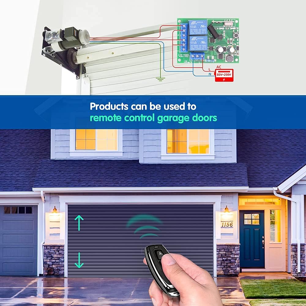
Figure 4: Remote control for lighting systems.
6. Operating Modes
The receiver supports three operating modes: Momentary, Toggle, and Latched. Each mode offers different control behavior for your connected devices.

Figure 5: Visual representation of operating modes.
6.1 Momentary Mode
In Momentary mode, the relay is activated only while the remote control button is pressed and held. Releasing the button deactivates the relay. This mode is suitable for applications like electric door locks or temporary power supply.
6.2 Toggle Mode
In Toggle mode, pressing the remote control button once activates the relay, and it remains active. Pressing the same button again deactivates the relay. This mode is ideal for controlling lights or other devices that require a persistent ON/OFF state.
6.3 Latched Mode
In Latched mode, pressing button 'A' on the remote activates Relay 1. Pressing button 'B' on the remote activates Relay 2 and simultaneously deactivates Relay 1. This mode is useful for applications where only one of two relays should be active at any given time, such as controlling the up/down movement of a motor where both directions should not be active simultaneously.
7. Programming the Remote Control
To pair your remote control with the receiver and set the desired operating mode, follow these steps:

Figure 6: Remote control programming steps.
-
Select Mode: Press the learning button on the receiver module a specific number of times according to the desired mode:
- For Momentary Mode: Press the learning button 1 time.
- For Toggle Mode: Press the learning button 2 times.
- For Latched Mode: Press the learning button 3 times.
- Pair Remote: Within approximately 3 seconds after the indicator light flashes, press the 'A' button on your remote control. The indicator light will flash again to confirm successful pairing for the first relay.
- Pair Second Button (if applicable): If you are using a 2-channel setup (e.g., for Latched mode), press the 'B' button on your remote control. The indicator light will flash again to confirm successful pairing for the second relay.
- Test: Test the remote control to ensure the desired operating mode is correctly set.
8. Resetting the Receiver
To clear all programmed remote controls from the receiver, follow these steps:

Figure 7: Resetting the receiver module.
- Press the learning button on the receiver module 8 times consecutively.
- The indicator light will flash rapidly and then turn off, indicating that all stored remote control codes have been cleared.
9. Remote Control Details
The remote control features two buttons (A and B) and is powered by a CR2032 lithium cell battery.

Figure 8: Components of the 2-button remote control.
9.1 Battery Replacement
If the remote control's range decreases or it stops responding, the battery may need replacement. To replace the battery:
- Carefully open the remote control casing.
- Remove the old CR2032 battery.
- Insert a new CR2032 battery with the positive (+) side facing up.
- Close the remote control casing securely.
10. Troubleshooting