
AENTIA Waterproof Wireless Remote Control DC 8V-80V 30A Radio Control Switch User Manual
AENTIA Waterproof Wireless Remote Control DC 8V-80V 30A Radio Control Switch
User Instruction Manual
1. Product Overview
The AENTIA Waterproof Wireless Remote Control Switch is designed for controlling electrical appliances in various environments, including outdoor and wet locations. It features a robust IP65 waterproof rating, a high-power 30A relay, and a 433MHz RF wireless control system, offering stable and reliable performance for applications such as water pumps, lighting, and irrigation systems.

Image 1.1: The AENTIA waterproof receiver unit and two accompanying remote control transmitters.
2. Package Contents
Verify that all items are present in the package:
- 1x Relay Receiver Unit
- 2x Transmitters (remote controls, batteries included)
- 1x Product Manual (this document)
3. Specifications
| Parameter | Value |
|---|---|
| Receiver Working Voltage | DC 8V~80V |
| Quiescent Current | <5MA |
| Max Current | 30A |
| RF Frequency | 433MHz |
| Working Temperature | -30~+80℃ |
| Receiving Sensitivity | >97dbm |
| Storage Remote Controls | Up to 20 pieces |
| Support Encoding | 1527 Leaning code |
| RF Operating Mode | ASK superheterodyne wireless reception |
| Receiving Range | Open space is more than 50 meters |
| Waterproof Grade | IP65 |
| Operating Modes | Momentary / Toggle / Latched Mode |
| Transmitter Battery | 2x CR2016 (included) |
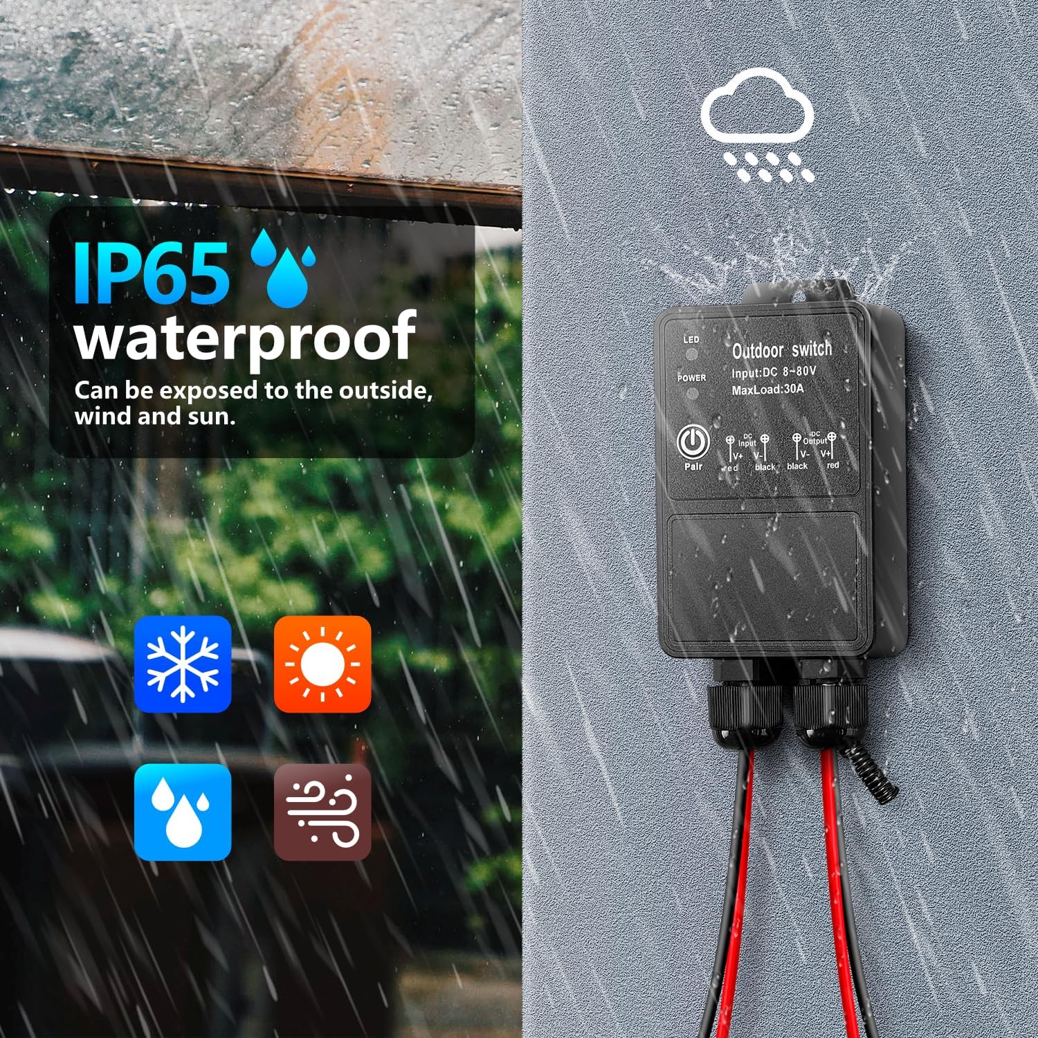
Image 3.1: The remote control offers a receiving range of over 50 meters in open spaces.
Image 3.2: The device features an IP65 waterproof rating, suitable for outdoor exposure to various weather conditions.
4. Installation and Wiring
The receiver unit is designed for easy integration into your electrical system. Ensure power is disconnected before performing any wiring.
4.1 Wiring Diagram
Connect the receiver between the power supply and the device to be controlled as shown in the diagram below. The input and output terminals are clearly marked for DC 8V-80V connections.

Image 4.1: Wiring connections for the DC 8V-80V receiver unit. Ensure correct polarity for input (V- V+) and output (V+ V-).
4.2 Wire Connection Steps
For secure and waterproof connections, follow these steps using the provided heat shrink solder connectors (if applicable):
- Step 1: Strip approximately 5-7mm of insulation from the wire ends at the link point.
- Step 2: Insert the stripped wire into the solder ring of the connector and move it to the center position. Ensure the wire does not extend beyond the hot melt glue.
- Step 3: Use a heat gun to evenly heat the connector. The solder will melt and flow, and the heat shrink tubing will shrink, creating a sealed connection.
- Step 4: After heating, allow the connection to cool for one minute before handling.

Image 4.2: Detailed steps for making secure wire connections using heat shrink solder sleeves.
5. Operating Modes
The receiver supports three operating modes: Momentary, Toggle, and Latched. The product is pre-set to Latched mode by default.
5.1 Momentary Mode
- Press and hold a button on the transmitter: The relay will turn on.
- Release the button: The relay will turn off.
5.2 Toggle Mode
- Press a button on the transmitter: The relay will turn on.
- Press the same button again: The relay will turn off.
5.3 Latched Mode (Default)
- Press the 'ON' button on the transmitter: The relay will turn on.
- Press the 'OFF' button on the transmitter: The relay will turn off.
6. Programming (Setup and Reset)
The receiver and transmitters need to be paired for wireless control. The operating mode can be adjusted during the setup process.
6.1 Setup Operating Mode
To set the operating mode and pair a transmitter:
- Press the learning button on the receiver:
- Once for Momentary Mode.
- Twice for Toggle Mode.
- Three times for Latched Mode.
- Press the 'ON' button on your transmitter. Wait for 3 seconds.
- Press the 'OFF' button on your transmitter. The setup is complete.
6.2 Resetting the Receiver
To clear all paired remote controls from the receiver's memory:
- Press the learning button on the receiver 8 times consecutively.
- The reset is successful. All previously paired remote controls will no longer function with this receiver.

Image 6.1: Instructions for programming the remote control to the receiver in Latched Mode and performing a full reset.
7. Wide Application
This remote control switch is suitable for a variety of indoor and outdoor applications due to its waterproof design and high power load capacity. Common uses include:
- Controlling water pumps for irrigation or fountains.
- Operating outdoor lighting systems.
- Managing exhaust fans in garages or warehouses.
- Controlling motors and other electrical equipment in farm or garden settings.
- Integration into wireless security alarm and video equipment systems.

Image 7.1: Examples of the diverse applications for the remote control switch in agricultural, residential, and industrial settings.
8. Safety Information
Please read and understand all safety instructions before installing or operating this product. Failure to do so may result in injury or damage to the product.
- Always disconnect power to the circuit before installing or servicing the receiver unit.
- Ensure all wiring connections are secure and properly insulated to prevent short circuits or electrical hazards.
- Do not exceed the maximum current rating of 30A for the receiver.
- While the product is IP65 waterproof, avoid prolonged submersion in water.
- Keep remote controls away from children.
9. Troubleshooting
If you encounter issues with your remote control switch, consider the following:
-
No response from receiver:
- Check power supply to the receiver.
- Verify that the transmitter batteries are not depleted.
- Ensure the transmitter and receiver are paired correctly (refer to Section 6.1). If unsure, perform a reset (Section 6.2) and re-pair.
- Check for obstructions or excessive distance between the transmitter and receiver.
-
Intermittent operation:
- Weak transmitter battery.
- Interference from other RF devices.
- Antenna on the receiver may need to be extended for better signal reception.
-
Incorrect operating mode:
- Re-program the receiver to the desired operating mode (refer to Section 6.1).
10. Warranty and Support
This product is covered by a standard manufacturer's warranty against defects in materials and workmanship. For warranty claims or technical support, please contact AENTIA customer service through your purchase platform or the official AENTIA website. Please retain your proof of purchase for warranty validation.